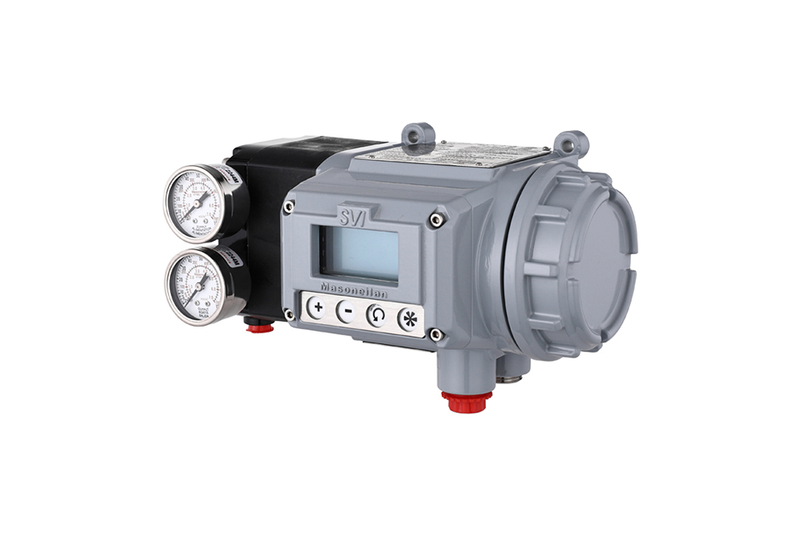
Masoneilan SVI 3 AP Advanced Performance Digital Valve Positioner
Masoneilan SVI3 Digital Valve Positioner
Accurate, Responsive and Reliable
The third generation Baker Hughes Masoneilan™ SVI™ is a user friendly digital valve positioner for pneumatic control valves. Utilizing advanced control and diagnostic algorithms, along with field-proven noncontact position sensing technology, the SVI delivers accurate, responsive, and reliable positioning performance.

Advantage
Reliable and accurate:Built on over 20 years of on-site validation of valve position sensing technology, control algorithms, and high-performance pneumatic design foundations
Improve factory efficiency:
- Use embedded key performance indicators (KPIs) to achieve intelligent troubleshooting
- Has cloning capability and can be hot plugged as needed
- A device that is widely applicable to various environments and applications can reduce spare parts inventory
- Low loss pneumatic
Easy to use:
- Automated one click debugging
- The local user interface provides complete configuration functionality without the need for additional tools/handheld devices
- Integrate with major control systems and asset management software systems
- Adopting a new modular structure and digital upgrade method, it is easy to upgrade on-site
- Integrated input/output, no need for additional external accessories
Function
- Smart Cal - One click setup and calibration
- The user interface features high contrast graphic displays and buttons, meeting the level of use in hazardous areas
- NAMUR NE 107 Warning
- Universal design for linear and rotary valve applications
- Durable and sturdy non-contact shielded magnetic travel sensor
- Optional corrosion-resistant stainless steel or aluminum industrial metal casing
- Encapsulation and coating of electronic components
- Comprehensive diagnosis: cycle counting, step testing, ramp testing, initial values, and system
Health Indicators
- Onboard valve position feedback and limit switch
- Stainless steel mounting bracket suitable for any valve actuator combination, fully backward compatible with SVI
- Equipped with explosion-proof and intrinsic safety universal labels, certified by the United States, Canada, ATEX, and IEC (models can be certified by various regions/countries)
- Compliant with HART ® 7 Communication Protocol
- Fully collectable actuator exhaust and locator exhaust
Shell/cover: chrome free copper (1) aluminum, ASTM A360; Optional 316L stainless steel
- Painting: Grey polyurethane and epoxy primer
- Protection: IP66 and NEMA 4X
Weight:
Aluminum -3.3kg (7.4 pounds)Stainless steel -6.26kg (13.8 pounds)
Material Science:
I/P motors and relays - composite polymer and stainless steel (300 and 400 series)Installation Kit - Stainless Steel (300 Series)
Input power and signal:
Minimum/maximum current: 3.2mA/22mARequired compliance voltage: 9Vdc @ 20mA, 11Vdc @ 4mA
- Termination: Screw type terminal
- Wire entry: Two 1/2NPT female connectors
Optional input/output signals:
Two configurable solid-state switches:- 1A – 30Vdc, Self-protecting
- Normally open or normally closed (when powered on)
- A 4 to 20 mA output - position retransmission
- A configurable digital input
- A Masoneilan remote position sensor input: 1k Ohm
- A 1-5V remote position sensor input
Communication, setup, and calibration:
- HART ® Protocol (7th edition)
- Can be integrated with major DCS systems, fully supporting DTM and EDD, including but not limited to:
- Emerson DeltaV / AMS
- Honeywell / FDM
- Yokogawa / PRM
- Optional local user interface with graphic LCD and keyboard, approved for use in hazardous areas
- Smart Cal one click calibration, including stop, air action, automatic adjustment, and scheduled adjustment
parameter set
- Environmental temperature and humidity limitations:
- Standard temperature: -40 ° C to 85 ° C
- (-40 ° F to 185 ° F), nitrile rubber diaphragm
- Optional extreme temperature: -55 ° C to 85 ° C
- (-67 ° F to 185 ° F), fluorosilicon diaphragm
100% relative humidity (non condensing)
Compatibility with tropical environments
- Antifungal properties comply with ASTM-G21
- Exposed circuits covered with antifungal coating
- The positive pressure shell is equipped with insect proof ventilation holes
EMC compliance standards:
- Compliant with IEC/EN61326-1 (2nd edition)
- Radiation: CISPR11 Class A
- Immunity: IEC/EN61000-4-2, 3, 4, 5, 6, and 8
- EMC 2014/30/EU Directive
Performance (2) complies with ISA S75.13:
- Accuracy of+/-0.5% of full scale
- Hysteresis+dead zone is+/-0.3% of full scale
- The repeatability is+/-0.3% of the full scale
- Power on (position control)<150ms
- Power off (no reset)<100ms
Valve actuator capability:
The non-contact shielded magnetic travel sensor has the following capabilities:- Linear motion: 0.25 "to 8" (6.4 to 200 mm)
- Rotation motion: 18 ° to 140 °
- Travel sensor resolution: 0.0125% (typical value - rotation)
Pneumatic (single action only)
- Dry oil-free air or sulfur free natural gas - regulated and filtered
- Gas supply pressure: up to 1.4 to 8.3 bar (20 to 120 psi)
- Optional exhaust manifold for 100% collection
Air delivery:
- 410 SLPM (14.5 SCFM) @ 30psi
Air capacity:
- Inflatable Cv=0.66
- Exhaust Cv -0.51
Steady state air consumption:
- 2.8 SLPM (5.9 SCFH) @ 30psi
- 3.4 SLPM (7.2 SCFH) @ 45psi
Advanced diagnosis:
on-line:- Schedule, cycle, closing/opening time, approaching closing time, and alarm
off-line:
- Slope testing: hysteresis, dead zone, accuracy, and linearity
- Step test: overshoot, response resolution, and dead time
- Valve initial value: spring range, friction, and seat curve
Online valve diagnosis:
on-line:- Friction, stick slip, spring range, error offset, RMS error, blockage detection, calibration error, and set value cyclic testing
Hazardous Area Certification:
ATEX, IECEx, Certification in the United States and Canada:- Fire/explosion prevention
- Intrinsic safety
- Dustproof combustion
- Increased safety type (e)
Technical Brief of Meisonilan SVI3 Digital Valve Positioner 2025-06-13
(1) Before installation, check that the product model, tag number, and specifications match the requirements. Inspect the entire valve for missing or loose parts.
(2) Prior to installation, clean the pipeline. Ensure there is sufficient straight pipe section at the valve inlet and install a filter. When connecting the valve body to the pipeline flanges, ensure coaxiality.
(3) Thoroughly clean the pipeline before installing the valve.
(4) The installation site should ensure the safety of personnel and equipment, facilitating operation, disassembly, and maintenance.
(5) The valve should be installed vertically upright on horizontal pipelines. If necessary, it can be installed at an angle, but horizontal installation should be avoided. For occasions with heavy valve weight or vibration, use a support frame.
(6) The medium flow direction must align with the arrow on the valve body. The air supply should be dry and oil-free. The valve should be used in environments with temperatures ranging from -20℃ to 55℃.
(1) Cleaning the Valve: For general media, cleaning with water is sufficient. For media harmful to health, first understand their properties and then select an appropriate cleaning method.
(2) Disassembly: Remove rust from exposed rusted parts first. Before derusting, protect the machined surfaces of precision parts such as the valve seat, valve plug, valve stem, and push rod. Use special tools when disassembling the valve seat.
(3) Valve Seat: Minor rust or wear on the sealing surface can be repaired by machining. If damage is severe, replace the seat. However, both repaired and replaced hard sealing surfaces must be lapped.
(4) Valve Stem: If the surface is damaged, it must be replaced.
(5) Damage to Push Rod, Guide, and Sealing Surfaces: Reverse-acting actuators must be replaced; direct-acting actuators can be reused after proper repair.
(6) Compression Spring: If there are cracks or other defects affecting strength, replace it immediately.
(7) Wear Parts: Packing, gaskets, and O-rings must be replaced entirely during each maintenance. Check the valve plug and diaphragm for cracks, aging, or corrosion that may cause future failures. Decide whether to replace them based on inspection results, but the diaphragm service life should not exceed 2-3 years.
(8) When reassembling the valve, ensure alignment. Tighten bolts diagonally and lubricate sliding parts. After reassembly, debug the valve according to the factory test items and methods. During this period, accurately adjust the packing compression force and the valve plug closing position.
- If the model has not been selected before ordering, please provide us with the operating parameters:
(1) Nominal diameter DN (mm);
(2) Nominal pressure (MPa or bar);
(3) Fluid properties (including medium temperature, viscosity, or acidity/alkalinity);
(4) Pressure before and after the valve (pressure differential);
(5) Requirements for flow characteristics;
(6) Materials of valve body and valve core;
(7) Connection type;
(8) Driving method (provide air supply pressure, driving voltage);
(9) Supporting accessories (for pneumatic valves, it is recommended that users install an air filter triplet and a 2-position 5-way solenoid valve);
(10) On-site working conditions. - If the product model of our company has been selected by the design unit, please order directly from our production department according to the model;
- When the application occasion is very important or the pipeline is relatively complex, please provide the design drawings and detailed parameters as much as possible, and our experts will review and check them for you.